Molecular Based Universal Logic Gates
30 May 2020
This post is a continuation of my blog Introduction-to-Molecular-Logic. We discussed there the various physical states upon which we can send a perturbation field thereby access quantum states ready to implement logic operations. Now let us focus our attention to one of this varities and see the implementation of Universal Logic Gates. To begin with, in this context, by Universal Logic Gates what we mean is the existing of full set of logic gates with which it is possible to implement all of the possible Boolean switching functions.
The full set of logics gates considered are AND, OR, and NOT. By using these three Universal Logic Gates we can create a range of other Boolean functions and gates. The aim of this article is thus to implement these three logic gates by an optically addressed quantum system.
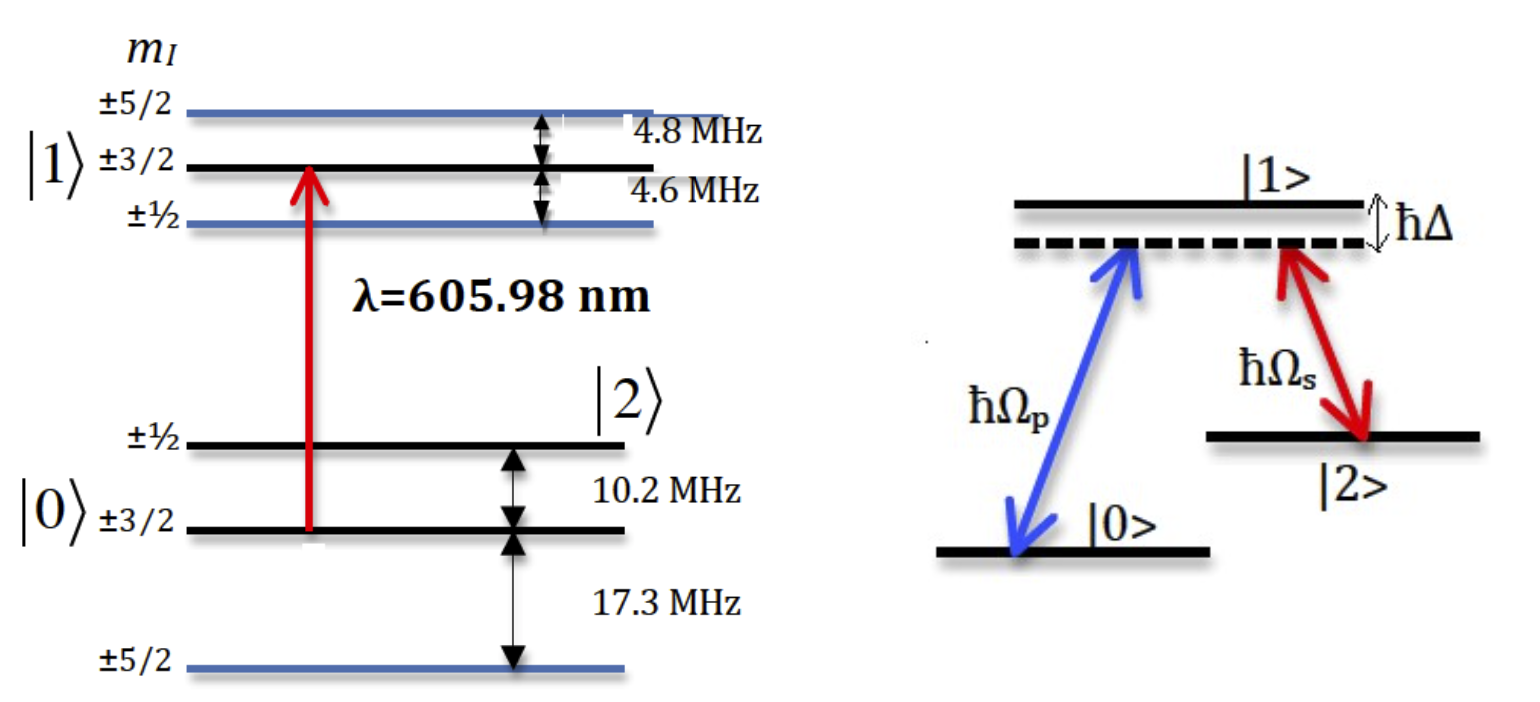
We consider an adiabatic population transfer in solids, specifically speaking on Rare-Earth-metal ions doped in solids. Rare-earth ions doped into inorganic crystal; exhibit optical transitions that do not occur in free ions. These are due to the interaction of the ions with the crystal field. The Energy level is shown in Fig. 1. The benefit of using Rare-Earth material is that: they exhibit sharp optical transitions and long decoherence times. This in turn facilitates the implementation of coherent adiabatic processes. It is worth noting that all the ground three states can be coupled to all three excited states, and altogether, nine transitions are possible.

The system we consider is a three level system, shown in fig. (1), whose states are \(|0\rangle , |1\rangle\) and \(|2\rangle\) with energy \(\hbar\omega_0,\hbar\omega_1,\hbar\omega_2\) respectively. Two lasers couples these three levels of the system. A pump pulse drives the transition between states \(|0\rangle\) and \(|1\rangle\). A second pulse, the Stokes pulse, drives the transition between \(|1\rangle\) and \(|2\rangle\). Thus we have transitions between states \(|0\rangle\) and \(|1\rangle\) , and between states \(|1\rangle\) and \(|2\rangle\); but no transition between \(|0\rangle\) and \(|2\rangle\), which is dipole forbidden.
By preparing the system to be initially on the ground state \(|0\rangle\), one can transfer \(100\%\) of the population to state \(2\rangle\). When we say population what we refer to is the mean photon number. To do so we couple the states, via the pulses, counter intuitively, that is we first couple the states \(|1\rangle\) and \(|2\rangle\) using the Stokes pulse, and later we couple states \(|0\rangle\) and \(|1\rangle\), using pump laser. STIRAP is robust in that it is insensitive to the decaying intermediate state \(|1\rangle\).
We won’t delve into the details of the dynamics as it is not the goal of the post. Suffice to say that we numerically solve the time-dependent Schrödinger equation for the probablity amplitudes and study the evolution of the wave function \(|\Psi\left(t\right)\rangle = \sum_i^{N-1} c_i\left(t\right)|i\rangle\)
\[i\hbar\frac{dc\left(t\right)}{dt} = H\left(t\right)c\left(t\right)\]It is worth recalling that for quantum systems with distinct states, external perturbations can change the state of the system. The three states of the system, i.e. \(|0\rangle , |1\rangle, |2\rangle\) respectively are the eigenstates of the unperturbed part of the Hamiltonian \(H_0\). Whereas \(H_I\) is the part of the Hamiltonian representing the interaction of the system with the laser field. Therefore, the total Hamiltonian, under Rotating Wave Approximation (RWA) and in the interaction picture, can be expressed as the sum of the two parts
\[H=\frac{\hbar}{2}\begin{bmatrix} 0 & \Omega_p\left(t\right) & 0\\ \Omega_p\left(t\right) & \Delta & \Omega_s\left(t\right) \\ 0 & \Omega_s\left(t\right) & 0 \end{bmatrix}\]The Unitary matrix \(U\) diagonalises the Hamiltonian into \(D = U^\dagger HU\) which is Adiabatic diagonal Hamiltonian. Where the transformation matrix \(U\) is given by
\[U=\begin{bmatrix} \sin\phi\sin\theta & \cos\phi & \sin\phi\cos\theta\\ \cos\theta & 0 & -\sin\theta \\ \cos\phi\sin\theta & -\sin\phi & \cos\phi\cos\theta \end{bmatrix}\]Moving into adiabatic basis requires mixing angle \(\tan\theta = \frac{\Omega_p\left(t\right)}{\Omega_s\left(t\right)}\)
One of the adiabatic basis is of interest to us regarding to population transfer, this is because it links the two ground states \(|0\rangle\) and \(|2\rangle\), that means we can use it as a railroad to transfer populations from one state to the other. As this basis doesn’t include the component from the excited state \(|1\rangle\), and note that this state is from which loss of population occur. For this reason the state is called Dark state: \(|\mathrm{Dark state}\rangle = \cos\theta |0\rangle -\sin\theta |2\rangle\)

Stimulated Raman adiabatic passage (STIRAP) is a protocol by which we are able to transfer population between two quantum states using coherent electromagnetic (light) pulses. In our case, the three level \(\Lambda\)-system shown in fig. 1, the two coupling laser pulses drive the transitions.
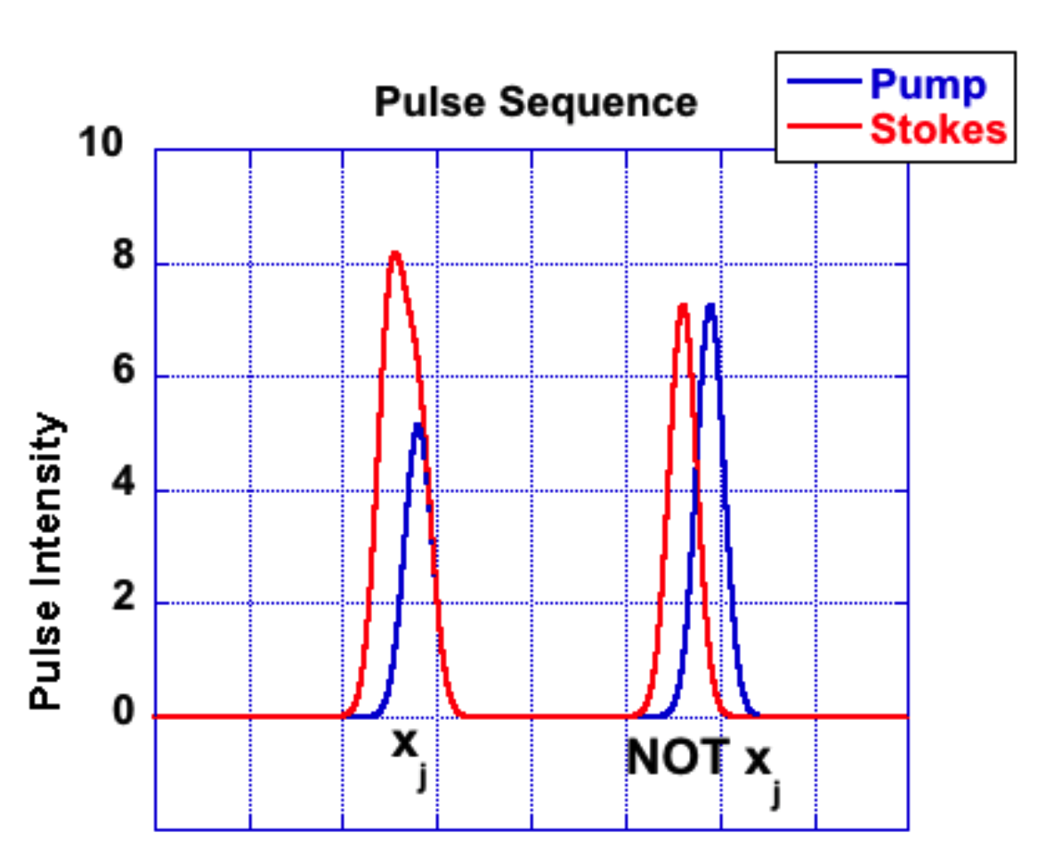
Let us say, initially we prepare all the populations to be in the ground state \(|0\rangle\), and if our goal is to transfer all this populations into state \(|2\rangle\) we demand our wavefunction \(|\Psi\left(t\right)\rangle\) to align with the dark state. Moreover the dark state has to be aligned initially with state \(|0\rangle\) and finally with \(|2\rangle\). We can see that this implies initially \(\cos\theta\rightarrow1\) and \(\sin\theta\rightarrow0\) (or initially \(\theta=0\)); after the pulse interacts with the system, that is finally, \(\cos\theta\rightarrow0\) and \(\sin\theta\rightarrow1\) (or finally \(\theta=\pi/2\)). Thus from the definition of the mixing angles, i.e \(\tan\theta=\frac{\Omega_p}{\Omega_s}\) we infer that we first shine the stokes laser that couples the two empty states \(|1\rangle\leftrightarrow|2\rangle\) and at a later time shine the pump light that couples the initial state to the intermediate state, i.e \(|0\rangle\leftrightarrow|1\rangle\). Thi kind of pulse protocol is seen on fig. 4, the second pulse sequence, in the figure, is STIRAP.
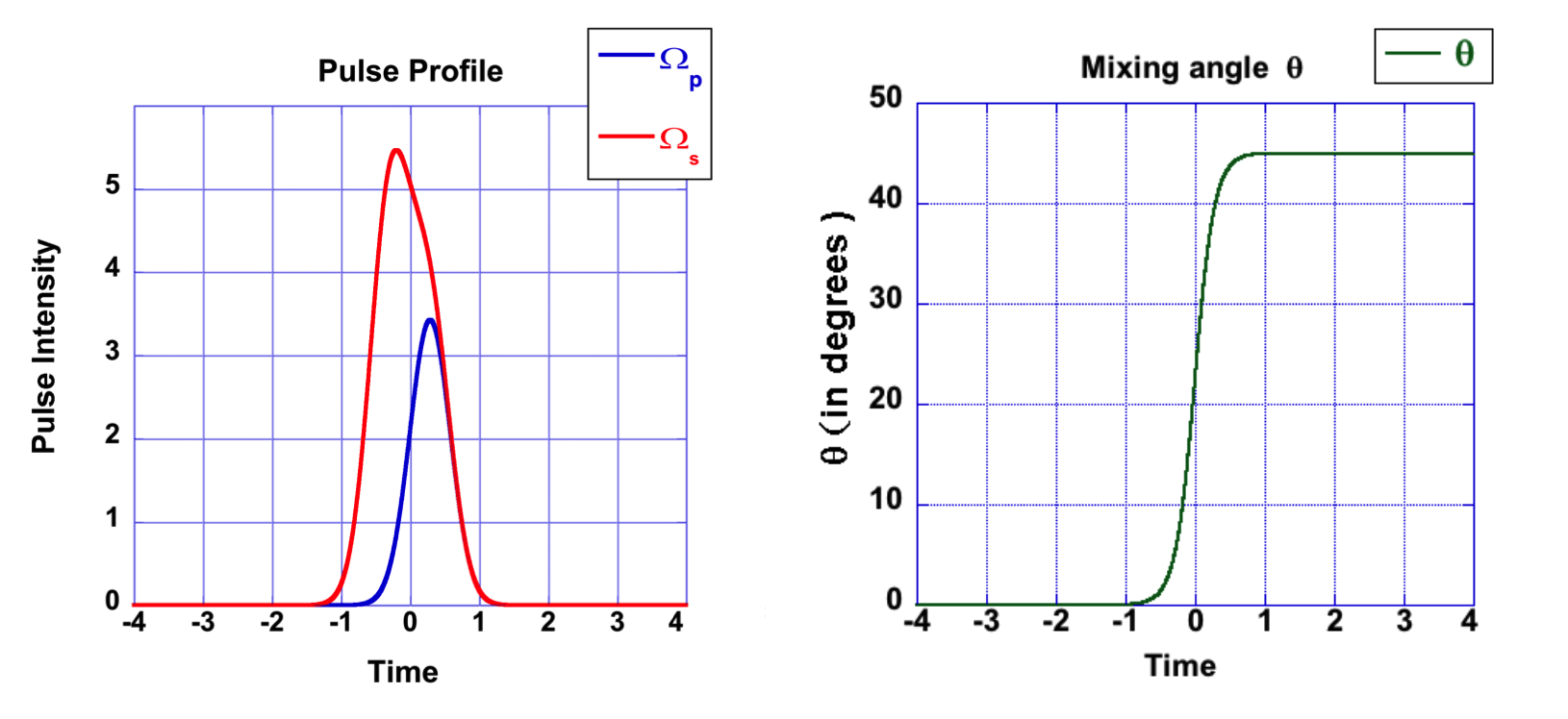
If on the other hand, instead of transferring all the population, we chose to distribute the population between the ground states, let us say half-half. Then, consequently, we need the dark state to initially align with ground state \(|0\rangle\) (like STIRAP), then later we want the dark state to consist of contributions from both ground states, in this case equal contribution. Mathematically put the conditions are: initially \(\theta=0\) and finally \(\theta=\pi/4\), as shown in fig 2. This variant of STIRAP is commonly known as Fractional-STIRSAP (FSTIRAP for short).
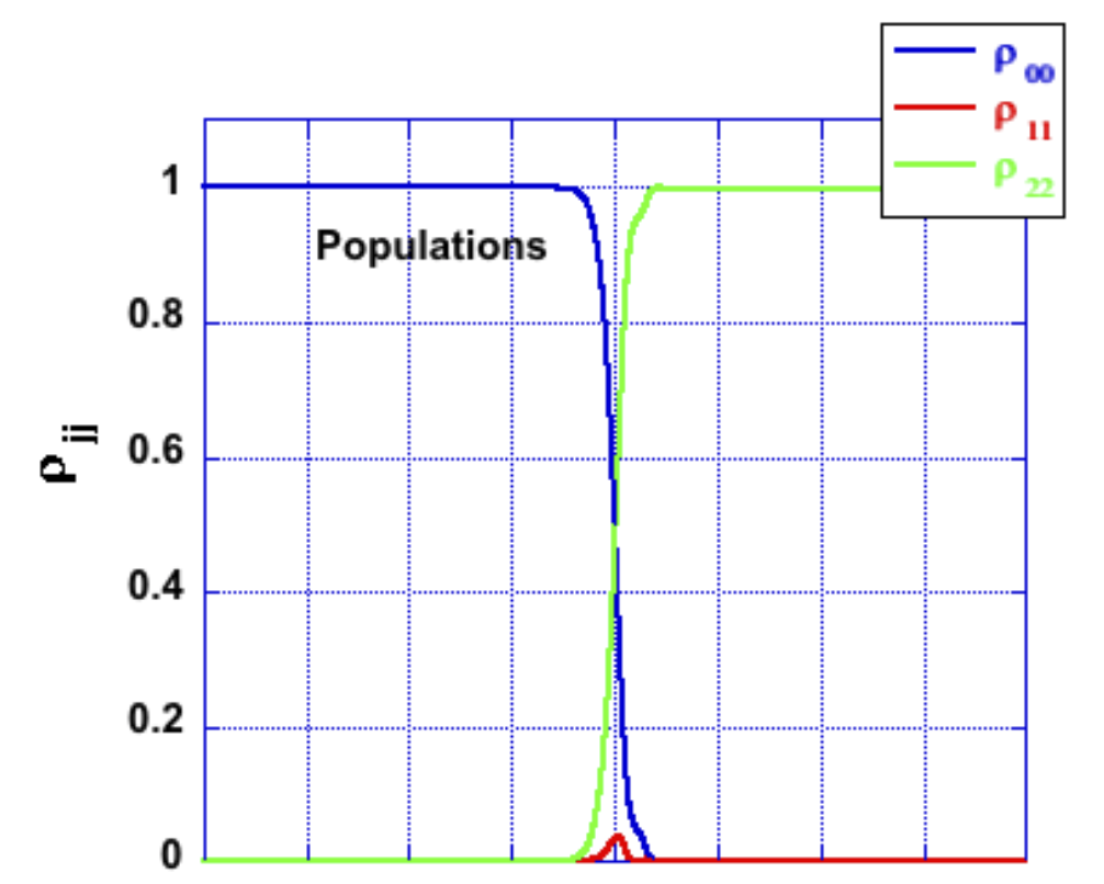
The Logic NOT Gate is the most basic of the logical gates and is often referred to as an Inverter. The STIRAP process where complete population from one state to another readily implements this logic gate. To show so, we need to define our input and output line in the physical system we are considering. The physics tells us that we can transfer all the population from the ground state into the excited state. If all the populations are on the ground state \(|0\rangle\) the scheme transfers it to state \(|1\rangle\). If on the other hand all the populations are prepared to be on state \(|1\rangle\) the STIRAP mechanism transfers it to state \(|0\rangle\). This dynamics seems to mimic the NOT logic Gate. The dynamics, which we get by solving the time dependent Schrödinger equation, representing the first row in the table 1, is shown in fig. 3.
The input and output will be reading the populations, i.e initial state and final state respectively. The logic assignment is as follows: if the population is in state \(|0\rangle\) the corresponding logic is logic value 0, and if the population is in state \(|2\rangle\) the corresponding logic is logic value 1. Therefore if we initially prepare the system to be on the ground state \(|0\rangle\) (i.e. logic value 0), then applying the STIRAP process takes all the population into state \(|2\rangle\) (i.e. logic value 1), and vice versa as shown in the truth table below.
| Input Intial state |
Output Final state |
|---|---|
| 0 (state 0) | 1 (state 1) |
| 1 (state 1) | 0 (state 0) |
    Table.1: Truth table of NOT gate, where n($$|n\rangle$$) represents n=logic assignment and
    $$|n\rangle$$=state of the system

Fig.3 -Population transfer with STIRAP. The horizontal-axis is time in reduced units [-4,4].
Python program to illustrate logic NOT gate
# Python program to illustrate logic NOT gate

def NOT(Input):
    if(Input == 0):
        return 1
    elif( Input == 1):
        return 0

if __name__=='__main__':


    print(" ================")
    print(" | Input |Output|")
    print(" ================")
    print(" | 0     | ",NOT(0),"  | ")
    print(" | 1     | ",NOT(1),"  | ")
    print(" ================")
================
 | Input |Output|
 ================
 | 0     |  1   |
 | 1     |  0   |
 ================
The AND gate is a basic digital logic gate that implements logical conjunction. A HIGH output (1) results only if all the inputs to the AND gate are HIGH (1). If none or not all inputs to the AND gate are HIGH, a LOW output results. The function can be extended to any number of inputs. In our physical system, the implementation of an AND gate can be achived by re defining the input reading along with the corresponding logic assignmnet. Note that a two input binary variable, where each variable can be either 0 or 1, have 4 possible input combinations. Therefore for the two inputs we use the two driving pulses, Stokes and Pump. The corresponding logic assignmnet will be the ON and OFF of these pulses, i.e. if pulse is turned ON the logic assignmnet is logic value 1, if the pulse is turned OFF logic assignmnet will be 0, see truth table 2. For the output we read the population on state \(|2\rangle\), provided we prepare the system to be intially in state \(|0\rangle\). Hence, if we have populations on that target state \(|2\rangle\), then the output is logic value 1, else it is 0.
The physics of this means that if both pulses are turned OFF (i.e. 00), nothing happens and we don’t read output and thus (0) -representing row one of the truth table. If pulse pump is turned ON but pulse Stokes is OFF (i.e. 01), state \(|2\rangle\) is disconneted and thus not enough population can be read so we will assign it logic value 0 -as indicated in row two of the truth table. By the same token one can reproduce row three of the truth table, (i.e. 10). If both pulses are ON (i.e.) the STIRAP mechanism will manage to transfer population from intial state to the target, thus logic value 1 –yielding the fourth row of the truth table. This completes the implementation of an AND gate using the physics of state-to-state coherent transfer.
| Input_1 Stokes |
Input_2 Pump |
Output state 2 |
|---|---|---|
| 0 | 0 | 0 |
| 0 | 1 | 0 |
| 1 | 0 | 0 |
| 1 | 1 | 1 |
Table 2: Truth table of an AND gate
These two gates AND and NOT consititute a complete set of logic gates. By cascading an AND gate with NOT we readily get NAND gate. Moreover, if we are able to implement an OR logic– as shown below. It provides an opportunity to concatenate it with a NOT gate and design a NOR gate.
# Python program to illustrate logic AND gate

def AND(input_1, input_2):

    if input_1 == 1 and input_2 == 1:
        return 1
    else:
        return 0

if __name__=='__main__':


    print(" =================")
    print(" | Inputs |Output|")
    print(" =================")
    print(" | 0,  0  | ",AND(0,0),"  | ")
    print(" | 0,  1  | ",AND(0,1),"  | ")
    print(" | 1,  0  | ",AND(1,0),"  | ")
    print(" | 1,  1  | ",AND(1,1),"  | ")
    print(" =================")
=================
 | Inputs |Output|
 =================
 | 0,  0  |  0   |
 | 0,  1  |  0   |
 | 1,  0  |  0   |
 | 1,  1  |  1   |
 =================
The OR gate is a digital logic gate that implements logical disjunction. A TRUE output (1) results if one or both the inputs to the gate are TRUE (1). If neither input is TRUE, a FASLE output (0) results. It is also worth mentioning that the logic function of OR finds the maximum between two binary input digits. In like manner logic AND function finds the minimum between the inputs.

Fig.4 -Pulse STIRAP and Fractional-STIRAP. The horizontal-axis is time in reduced units [-4,4]
We now use pulse sequence of two laser pulse, each can be of STIRAP (SP) pulse profile or FSTIRAP (FSP) pulse profile, yielding 4 input possible combinations. We assign logic 0, when we apply the SP pulse and logic 1 for FSP pulse profile. Because we have two inputs (the pulse sequence), and because each can be either 0 or 1, we have \(2^2=4\) possible combination of inputs as seen in the truth table. Once again, the system is initially prepared to be on the ground state \(|0\rangle\), we apply the first pulse profile, and wait some time \(t_1\) before applying the second pulse profile. As our output we follow the evolution of the observable vector at each stage (before, during, and after pulse is applied). But for the purpose of logic we don’t use the observables’ evolution during the interaction of the system with the pulses. We will follow the evolution of the observable vector before and after the system interacts with each laser pulse profile. It is our aim to make connection between these evolution paths and an OR logic gate.
| Input_1 Pulse_1 |
Input_2 Pulse_2 |
Output Population on state 2 |
|---|---|---|
| 0 | 0 | 0 |
| 0 | 1 | 1 |
| 1 | 0 | 1 |
| 1 | 1 | 1 |
The two sequential pulses are our two inputs. The inputs for the third row is shown in fig. 4. As our output we read the population on state \(|2\rangle\). We set a threshold for the population, that is if the readings on the populations on state \(|2\rangle\) are equal to or greater than 0.35 the logic assignmnet will be logic value 1, else it is 0.
As in previous cases we now also assume initially the populations are preparaed to be on state \(|0\rangle\). The application of the first SP pulse will transfer all the population onto state \(|2\rangle\). If we apply a second sequence of SP pulse it brings all the populations back to state \(|0\rangle\) – this phenomenon is represenetd in the first row of the truth table in table 3. If, on the other hand, the second pulse sequence is of FSP scheme, then it will distribute the population between states \(|0\rangle\) and \(|2\rangle\). As we still have readings of population on state \(|2\rangle\) thus the output is logic value 1; this process is exhibted on row 2 of the truth table. The third and fourth rows consists at least one of the pulse sequence to be FSP ensuring the creation of superposition between states \(|0\rangle\) and \(|2\rangle\), thereby allowing population on state \(|2\rangle\).
Python program to illustrate logic OR gate
# Python program to illustrate logic OR gate

def OR(input_1, input_2):
    if input_1 == 1:
        return 1
    elif input_2 == 1:
        return 1
    else:
        return 0

if __name__=='__main__':


    print(" =================")
    print(" | Inputs |Output|")
    print(" =================")
    print(" | 0,  0  | ",OR(0,0),"  | ")
    print(" | 0,  1  | ",OR(0,1),"  | ")
    print(" | 1,  0  | ",OR(1,0),"  | ")
    print(" | 1,  1  | ",OR(1,1),"  | ")
    print(" =================")
=================
 | Inputs |Output|
 =================
 | 0,  0  |  0   |
 | 0,  1  |  1   |
 | 1,  0  |  1   |
 | 1,  1  |  1   |
 =================
Several challenges can be mentioned for the realization of such logic gates. One of these could be the how to of manufacturing such optical gates using the current industry. Another set back, which as you might have noticed is excluded from the present discussion, is the effect of noise. It should be stressed that noise brings a challenge as it washes out the stored information. The recommendation, at least for now, is to perform the proposed logic operations within the time window. That is a widow that exists before the effect of the environment destroyes the information. It is worth mentioning that there are efforts undergoing to control, or at least minimize, the role of noise in the dynamics.